Raspberry Pi-2 Laptop
- City: Vancouver
- Listed: 2017-07-17 10:50 pm
- Expires: 7083 days, 6 hours
Description
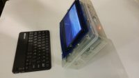
This is a laptop I made with a Raspberry Pi-2, and a plastic case from an old Arduino kit. I used two 6-volt batteries in series for a 12 volt power source, (because I couldn’t find a 12 battery the right size.) Then I used a Buck converter from Ebay to step 12 volts down to 5 volts to power the display and the Raspberry Pi. The Buck converter is adjustable so I adjusted it a bit high (5.33 volts)to account for losses when the battery gets low. The Buck converter works great in this application because even when the battery starts running low.. down to 11 or 10 volts… the output to the Raspberry Pi still remains at 5 volts.
Buck Converter:
http://www.ebay.ca/itm/252676990550
Display:
http://www.ebay.ca/itm/172077394142
You can see in the picture it draws .70 amps from the battery which is at 12.5 volts and steps it down to 5 volts for the second splitter which powers both the display and the Raspberry Pi. You can also see that the display and the Pi are together drawing .82 amps at 5.06 volts in the picture. Here is link to the USB splitter with built in voltage and current display.
http://www.ebay.com/itm/1PC-New-LED-USB-Detector-Voltage-Current-Meter-Tester-Power-Volt-Amp-Hottest-/141606762253?
It’s nice to know how much current the display and Raspberry Pi are drawing so you can monitor the battery condition. I get about 3 hours of laptop use with this setup. The keyboard is a Bluetooth device which connects up to the Raspberry Pi3’s built-in Bluetooth.
In the last 2 pictures I’ve showed the connections for setting up the systems power wiring and connected to a spare Raspberry Pi just for demo. You can see that the R-Pi is drawing .44 amps at 5.19 volts, and that the converter is sending out 5.33 volts. You can select the converter to display the input voltage from the battery or the output voltage to your load… in this case the load is the USB splitter which runs the R-Pi. I had to cut a USB female plug cord so I could connect the wires to the output pins of the 12 volt converter, and this is shown in the last picture.
3666 total views, 2 today


